Introduction
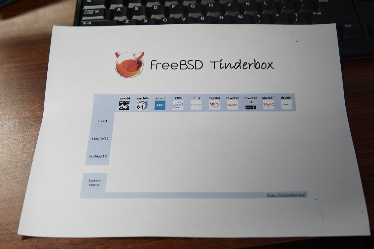
FreeBSD now has a number of continuous integration jobs on Jenkins CI to build and test FreeBSD on various architectures, and the newly implemented Tinderbox View presents a high-level, simple dashboard to the real-time FreeBSD CI build status.
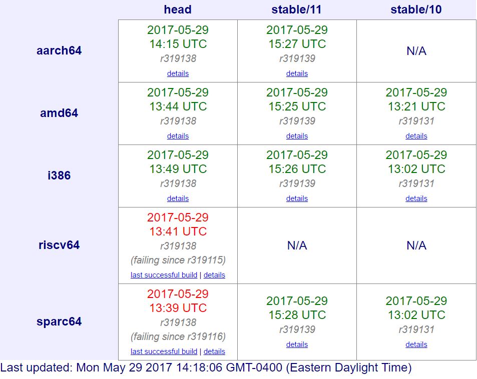
This display is so useful that we wanted a physical version in our office to monitor the build status more easily. What started as a side project during my first few weeks of interning at The FreeBSD Foundation, has become a useful LED display of the current FreeBSD CI (continuous integration) build status, and is running 24/7 in the Foundation Kitchener office, proudly running FreeBSD on a BeagleBone Green.
Prerequisites
- A working installation of FreeBSD
- BeagleBone Green with a 4GB micro-SD card, a serial cable and Internet connection
- An addressable LED RGB strip. This project uses an APA102 LED strip from Sparkfun
Steps
Install FreeBSD on the micro-SD card
1. Build or download a FreeBSD image
To get started, you can download an image from the FreeBSD Snapshot site with filename labeled as BeagleBone. In this case, we download:
FreeBSD-12.0-CURRENT-arm-armv6-BEAGLEBONE-20170519-r318502.img.xz
then extract it:
$ unxz FreeBSD-12.0-CURRENT-arm-armv6-BEAGLEBONE-20170519-r318502.img.xz
to get the .img image.
You can always choose to build FreeBSD from source code if you want to experience the latest changes for the support of BeagleBone and are comfortable with the process. Crochet is the tool to use, and you can find a detailed guide on GitHub.
2. Install the image
The dd(1) utility is used for raw data copying such as, initializing a disk from a raw image.
dd requires specifying if (input file), of (output file) and bs (copy block size). These arguments should be changed to match the actual file and device name.
$ dd if=FreeBSD-BeagleBone.img of=/dev/da0 bs=8m
Specifying a block size is not necessary, but the default setting will result in very slow operation.
If you are not sure of which device it is, simply run:
$ tail /var/log/messages
right after inserting the micro-SD, or:
$ sudo camcontrol devlist
to see the corresponding device name.
After the operation finishes, you can insert the micro-SD card into the BeagleBone.
Boot the BeagleBone Green
1. Connect the serial cable
A serial cable might not be necessary as you can wait until it boots and try to ssh to it (the system configuration might prevent you from logging in as root with ssh though). However, since BeagleBone Green doesn’t have an HDMI output, you can see what is going on through the whole booting process with a serial cable, making it much easier to diagnose if something goes wrong.
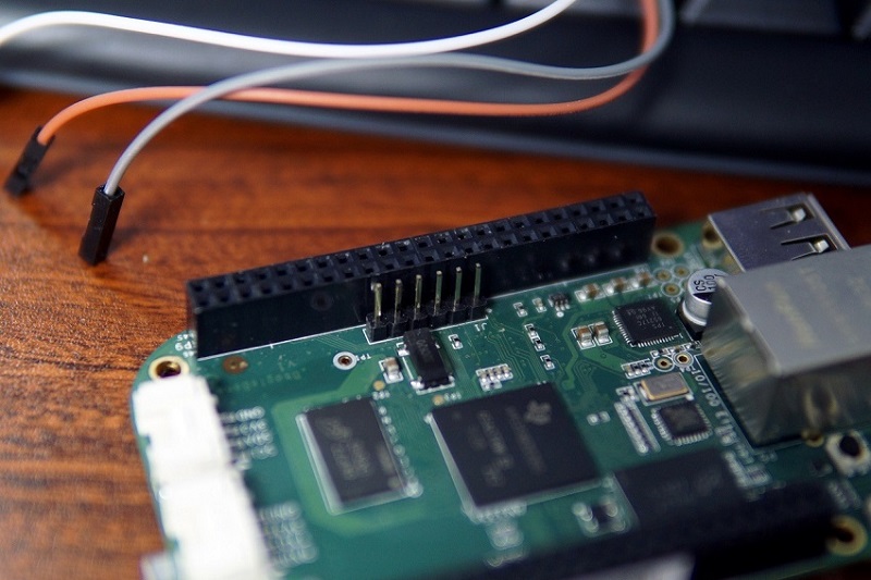
The serial console of BeagleBone Green is exposed on a 6-pin header.
The built-in cu(1) utility can be used for serial communications. cu can only access the /var/spool/lock directory via user uucp and group dialer. Use the dialer group to control who has access to the modem or remote systems by adding user accounts to dialer using pw(8):
$ sudo pw groupmod dialer -m guangyuan # Use your own username
Then log out and log in again to make the above change live.
Connect the USB to TTL cable to BeagleBone and computer, then run the cu utility and specify the line speed of 115200 baud.
$ cu -s 115200 -l /dev/cuaU0 # Or appropriate device
You won’t see any output yet.
Note: Using sudo to use cu is not a good practice, instead you should add the user to the dialer group as above stated, or grant everyone’s access as an alternative by running:
$ chmod 4511 /usr/bin/cu
For more info about serial communications, see FreeBSD Serial Communications.
2. Boot up and log in
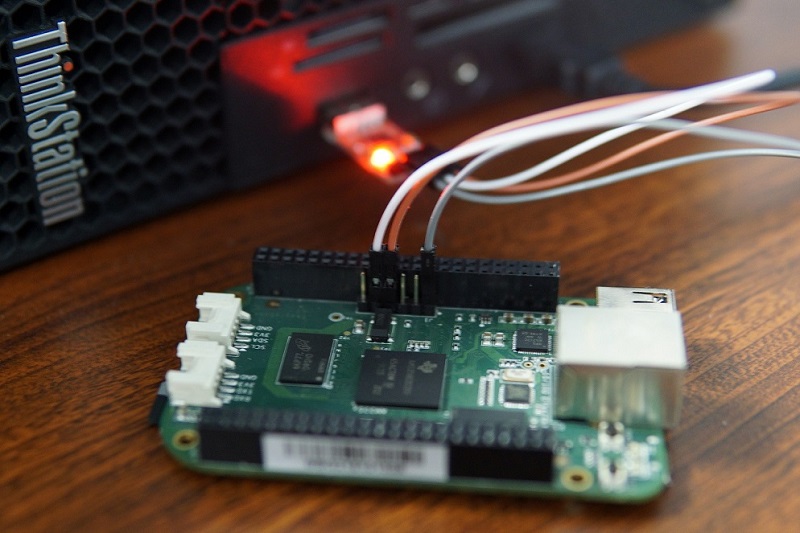
The BeagleBone Black can boot from either the onboard eMMC or a micro-SD card. By default it boots from eMMC. To boot from micro-SD, first hold down the boot switch, then apply power. Don’t release the button until you see it starts booting FreeBSD (or count to 5).
(image from http://wiki.seeed.cc/BeagleBone_Green/)
The boot switch is just above the micro-SD slot.
After booting, log in as root (the default password is “root” as well).
Tip: Making a BeagleBone Black Always Boot From the Micro-SD
The AM335x chip on board actually boots from the first partition that has the active flag set. After using the “holding the boot button” method described above to boot FreeBSD and log in as root, you will be able to turn off the bootable flag of the onboard eMMC to make it always boot from the micro-SD:
$ gpart unset -a active -i 1 mmcsd1
To restore this change and make the eMMC available again do:
$ gpart set -a active -i 1 mmcsd1
Alternatively, you can copy the FreeBSD image to eMMC so no pressing the button is needed.
3. Sync system clock
The system may refuse to proceed on some commands if the system clock is wrong.
In FreeBSD, it is recommended to use both ntpdate and ntpd. ntpdate will set the clock when you first boot so it’s close enough that ntpd will work with it. Add the following to /etc/rc.conf:
 ntpd_enable="YES"
 ntpdate_enable="YES"
Then read through /etc/ntp.conf. It’s pretty well documented so it should be obvious what to set.
4. Enable root login via ssh
Open /etc/ssh/sshd_config and change this line:
#PermitRootLogin no
to:
PermitRootLogin yes
then, restart the ssh daemon:
$ /etc/rc.d/sshd restart
and you will be able to login as root via ssh.
Test the GPIO on board
Let us start from mastering the control of an external LED.
1. GPIO wiring
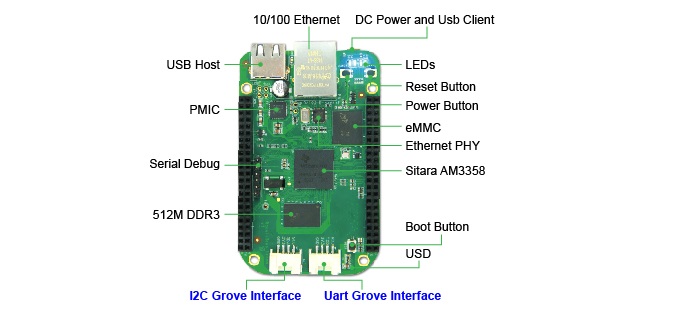
First let’s take a look at Beaglebone Green’s pin map:
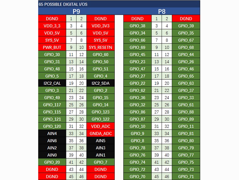
(image from http://wiki.seeed.cc/BeagleBone_Green/)
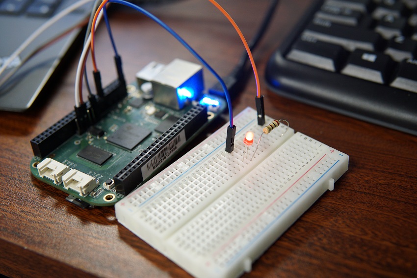
Now we connect a LED and a 200Ω resistor using jumper wires.
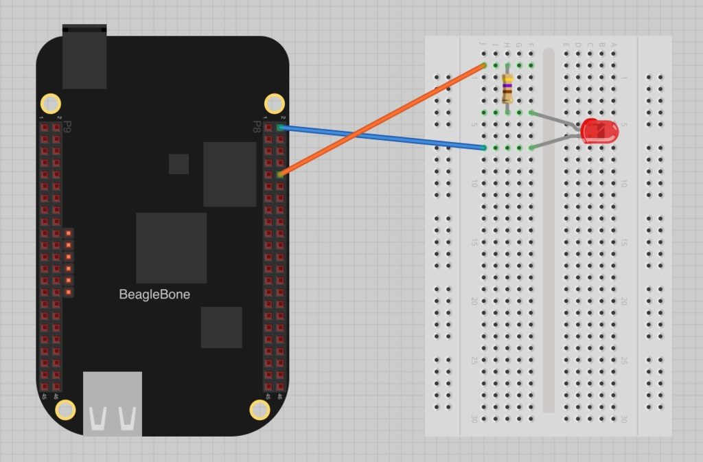
(image from https://learn.adafruit.com/blinking-an-led-with-beaglebone-black/wiring)
The top two connections on the BeagleBone expansion header are both GND. The other lead is connected to a pin of your choice.
2. Send test signals
No programming is required at this moment, as FreeBSD provides us with the gpioctl(8) utility which could be used to list available pins and manage GPIO pins from userland.
Let’s list all the available pins defined by device /dev/gpioc0:
$ gpioctl -f /dev/gpioc0 -l
By default, all the IO pins are set to be inputs. This does not work for our LED. Instead, we need the pin it is connected to be an output, so we configure that:
$ gpioctl -f /dev/gpioc0 -c 3 OUT # Assuming pin 3 is the one used
The pin should be output mode now, but the LED should still be off. To turn it on, type:
$ gpioctl -f /dev/gpioc0 3 1 # Assuming pin 3 is the one used
Now we have set the logical value of pin 3 to be 1, and the LED is on! To turn it off again, type:
$ gpioctl -f /dev/gpioc0 3 0 # Assuming pin 3 is the one used
You can try blinking the LED by writing a bash script with a simple loop.
SPI bit banging
Awesome! GPIO is working well with BeagleBone, it’s time to start using the addressible LED strip.
The LED RGB strip we used is packed with 60 APA102s and can be controlled with a standard SPI interface. However, at this moment, FreeBSD has no userland support for SPI devices. We used Bit banging to simulate the SPI Protocol as a workaround.
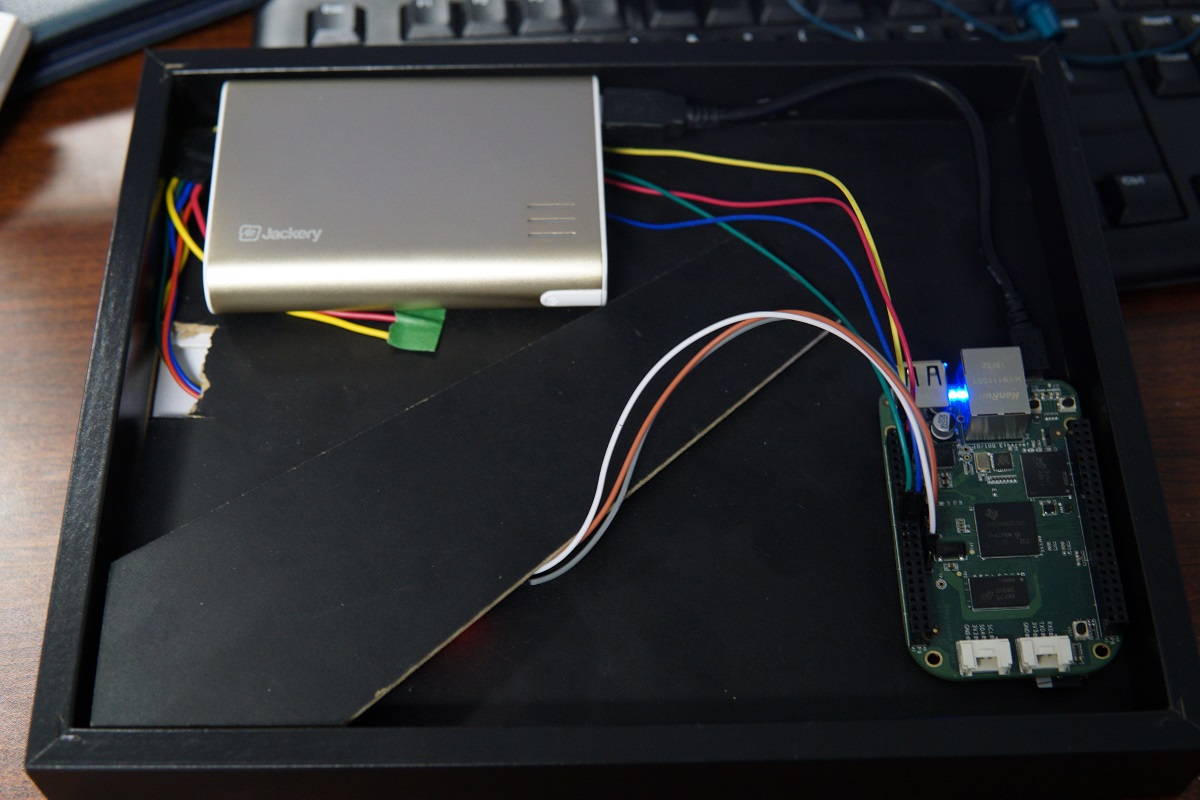
1. Wire LED strip to the BeagleBone
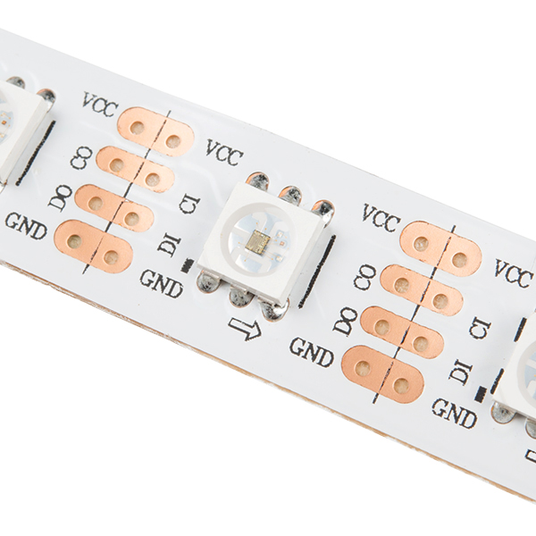
(image from https://www.sparkfun.com/products/14015)
Using the pin map, we connected:
VCC -> SYS_5V
CI -> GPIO of your choice
DI -> GPIO of your choice
GND -> DGND
2. Install Python development environment
We used Python and the fbsd_gpio python bindings for the code. Install Python and pip first, and then cffi and fbsd_gpio libraries via PyPI.
 $ pkg install python py27-pip
 $ pip install --user cffi fbsd_gpio
Note: You may encounter an error when using `pip` which will give an error like:
unable to execute '/nxb-bin/usr/bin/cc': No such file or directoryThis is because FreeBSD uses some cross-compile tools on some embedded platforms (mips, arm, aarch64, etc.) which aren’t used in this setup and will cause build errors. The bug has not been fixed yet (Bug 208282), but in the meantime, we could just change all references in /usr/local/lib/python2.7/_sysconfigdata.py as a workaround:
$ sed -i '' 's/\/nxb-bin\/usr\/bin\/cc/\/usr\/bin\/cc/g' /usr/local/lib/python2.7/_sysconfigdata.py
3. Write SPI bit banging functions
There is a SPI bit banging abstraction in the fbsd_gpio package used below but has not been documented yet. You can use that abstraction and skip this step, or you can still choose to follow it as a good learning practice.
Import the library and create a controller:
 from fbsd_gpio import GpioController
 gpioc = GpioController(0) # Using gpio controller unit 0 (/dev/gpioc0)
Set which pins we are using:
 SCLK = 2 # CI (Blue)
 MOSI = 3 # DI (Green)
Note:
SCLK: Serial Clock (output from master)
MOSI: Master Output Slave Input (data output from master), or DI from LED
Provide SPI init and write functions (it’s better to use bitwise operators when working with bits):
 def spi_init():
     gpioc.pin_output(SCLK)
     gpioc.pin_output(MOSI)
     gpioc.pin_set(SCLK, 0)
     gpioc.pin_set(MOSI, 0)


 def spi_write_byte(b):
     for i in xrange(7, -1, -1):
         gpioc.pin_set(SCLK, 0)
         gpioc.pin_set(MOSI, (b >> i) & 1)
         gpioc.pin_set(SCLK, 1)


 def spi_write(buf):
     for i in buf:
         spi_write_byte(i)
A complete description of fbsd_gpio can be found in the fbsd_gpio documentation on PyPI.
4. Work with APA102 LEDs
Once we set up the SPI functions, we were ready to send SPI data, but first we needed to figure out what to send in order to light up the LEDs we want. Follow the APA102 Manual to find out the data format:
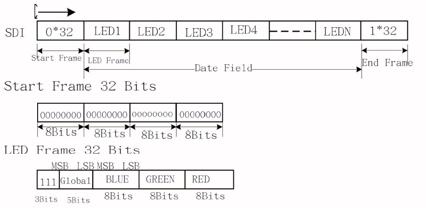
(image from https://cdn-shop.adafruit.com/datasheets/APA102.pdf)
Each update consists of a start frame of 32 zeroes, 32 bits for every LED, and an end frame of 32 ones. So our send function will most likely to work as follows:
 # Start Frame
 spi_write([0b00000000, 0b00000000, 0b00000000, 0b00000000])

 # LED Frames
 spi_write([0b11111111, 0b00000001, 0b00000000, 0b00000000]) # First LED, brightness full, blue
 ...

 # End Frame
 spi_write([0b11111111, 0b11111111, 0b11111111, 0b11111111])
Read this article if you want to Understand the APA102 “Superled” better.
Display the status
1. Get data from Jenkins
Many objects of Jenkins provide remote access APIs. We used the provided Python one to get status of all jobs:
 import ast
 import urllib
 JENKINS_URL = "https://ci.freebsd.org/api/python?tree=jobs[name,color]"
 data = ast.literal_eval(urllib.urlopen(JENKINS_URL).read())["jobs"]
This is how the data will look like:
 {
   "_class" : "hudson.model.Hudson",
   "jobs" : [
     {
       "_class" : "hudson.model.FreeStyleProject",
       "name" : "FreeBSD-doc-head",
       "color" : "blue"
     },
     {
       "_class" : "hudson.model.FreeStyleProject",
       "name" : "FreeBSD-doc-head-igor",
       "color" : "blue_anime"
     },
     ...
   ]
 }
And the latest status could be extracted from color attribute in data["jobs"] and stored in a dictionary called status.
The Jenkins API manual can be found in the Jenkins CI API reference.
2. Light up the LEDs
Recalling the APA102 data format, we wrote some predefined data frames:
 # Variables
 BRT = 224 + 16 # Brightness, 0~31 decimal

 # Predefined data frames
 START_FRAME = [0, 0, 0, 0]
 END_FRAME = [255, 255, 255, 255]
 BLUE_LED_FRAME = [BRT, 1, 0, 0]
 GREEN_LED_FRAME = [BRT, 0, 1, 0]
 RED_LED_FRAME = [BRT, 0, 0, 1]
 YELLOW_LED_FRAME = [BRT, 0, 1, 1]
 OFF_LED_FRAME = [224, 0, 0, 0]
and some send functions:
def led_send_start():spi_write(START_FRAME)def led_send_end():spi_write(END_FRAME)def led_send(status):if status in ["blue", "blue_anime"]:spi_write(GREEN_LED_FRAME)elif status in ["red", "red_anime"]:spi_write(RED_LED_FRAME)elif status in ["dne"]:spi_write(OFF_LED_FRAME)else:spi_write(YELLOW_LED_FRAME)def led_send_all(jobs):led_send_start()for job in jobs:led_send(job["status"])led_send_end()
so that once we updated the status dictionary, we were able to use led_send(status) to update the display:
 if __name__ == "__main__":
     spi_init()
     while True:
         status = ... # Fetch the data
         led_send_all(status) # Update
         time.sleep(10) # or any other interval
3. Let them blink!
Now the display works really well with the static states of the job. However, we noticed that the blue_anime and red_anime colours in Jenkins, which indicate a project is in the process of building (and should be blinking), were treated as static status in the code.
How can we make the LEDs blink while keeping their current status? We added a blink_flag boolean inside the loop, reversed it each time, and decided if we should turn the lights off based on that.
Add the flag to the LED updating loop:
 blink_flag = False
 while True:
     status = ... # Fetch the data
     blink_flag = not blink_flag
     led_send_all(status, blink_flag) # Update
     time.sleep(10) # or any other interval
and reflect changes in the send function:
 def led_send_all(jobs, blink_flag):
     led_send_start()
     for job in jobs:
         if "anime" in job["status"]:
             if blink_flag:
                 led_send(job["status"])
             else:
                 led_send("dne")
          else:
              led_send(job["status"])
     led_send_end()
We considered splitting the data fetching and the LED updating process, since blinking requires updating the LEDs every 0.5s, but fetching data should be every 20s or even longer. This could be achieved by simply adding a nested loop (for example, 40 led updates, 1 data updates, loop), but I chose to use threading so both jobs will not affect each other if one gets stuck.
Move the LED updating process into a controller class and run it separately:
import threading
class Led_controller(threading.Thread):
    def run(self):
        blink_flag = False
        while True:
            blink_flag = not blink_flag
            led_send_all(status, blink_flag)
            time.sleep(0.5)

if __name__ == "__main__":
    spi_init()
    led_controller = Led_controller()
    led_controller.start()

while True:
    status = ... # Fetch the data
    time.sleep(10) # or any other interval
And the LEDs should be able to blink at an interval of 0.5s.
Add some final touches
We cut the strip to parts and stuck them inside a picture frame.
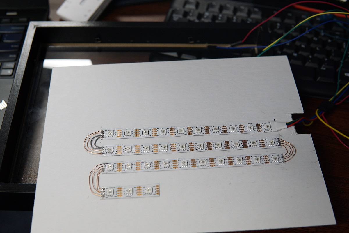
Looking good!
Further reading
My implementation of this project: yzgyyang/freebsd-ci-ledstrip
FreeBSD’s support for BeagleBone: FreeBSD/arm/BeagleBoneBlack
A guide of building, installing and updating FreeBSD on a BeagleBone:
Getting Started with FreeBSD on BeagleBone Black
Official BeagleBone Green Document: BeagleBone Green
Thanks
I would like to thank my supervisor Ed Maste for his guidance and support on my work. I would also like to thank Siva Mahadevan, my colleague and friend, for the help and useful suggestions.
– Contributed by Guangyuan (Charlie) Yang